Spectrum 48K Repair – Part 3

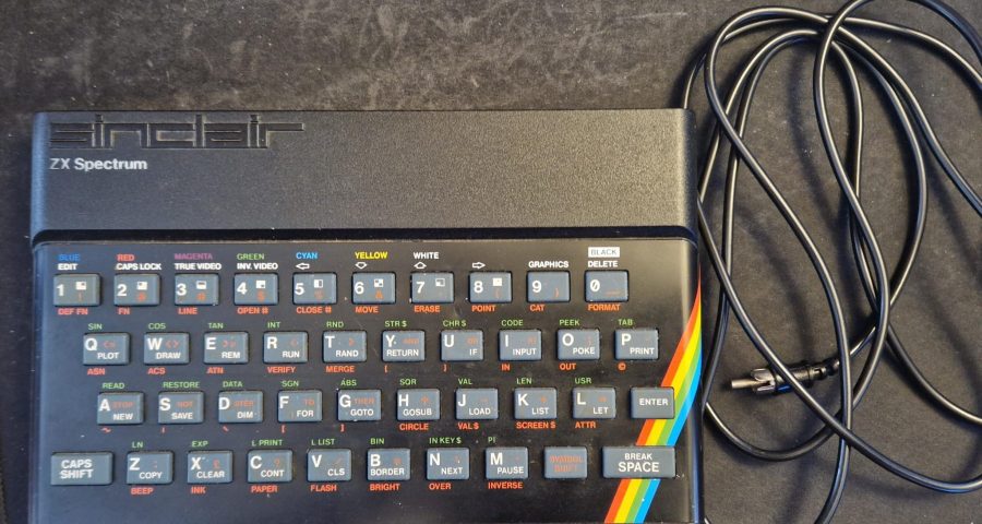
Welcome to part 3 of this series where I try and repair my first ZX Spectrum.

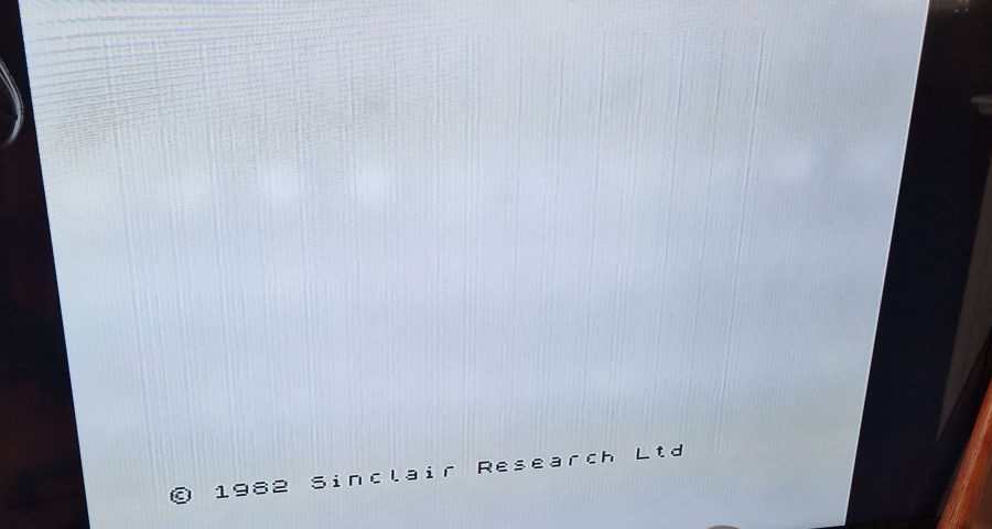
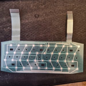
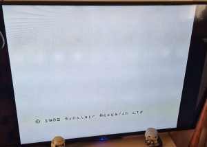
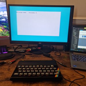
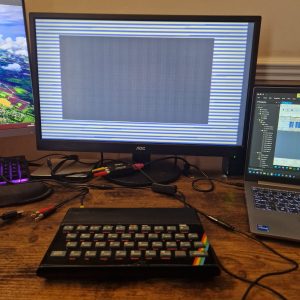
So far, we’ve installed the Composite Mod and replaced the broken keyboard membrane. Unfortunately, the speccy was crashing when keys were being pressed and giving this image:


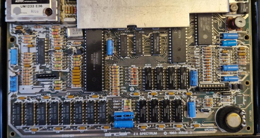
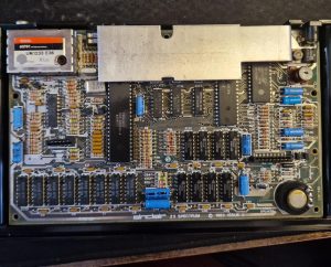
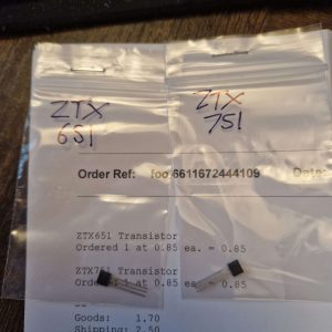
Lee from the More Fun Making It YouTube channel, kindly pointed me towards transistor TR4 or TR5 being the issue. So off the back of his advise, I ordered the appropriate replacements from Retroleum
ZTX 651 is the TR4 replacement
ZTX 751 is the TR4 replacement

Not knowing which one was at fault I did a quick test – TR5 gave me some connectivity, but TR4 didn’t – so I decided to replace TR4 first

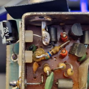
Once desoldered I had a quick look at it

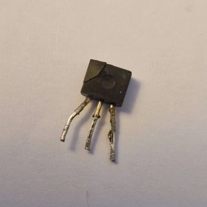
Yep, that is definitely dead – that crack at the top left corner shouldn’t be there!

I put in the replacement transistor, and after checking there were no solder bridges or splashes, I re-attached the keyboard and powered it up…

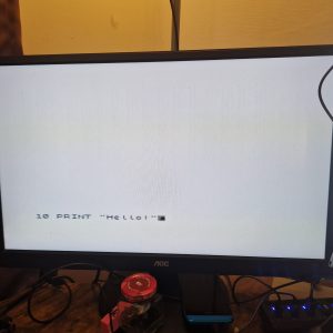
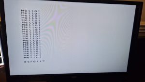
This is as far as we got the last time, but when I pressed enter the screen went all funky.. what will happen this time

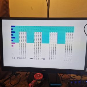
Well that looks promising – I added a 20 GO TO 10 statement and ran the program

Looking good! No sign of any screen corruption and the speccy didn’t lock up

Now it was time for to do a quick RAM test to ensure it was seeing all the RAM.. I was fairly confident that it was seeing at least the 16K of lower ram, but I wanted to ensure it was seeing all of the upper ram as well.
A simple line of BASIC can get the RAM count:
PRINT PEEK 23732+255*PEEK 23733
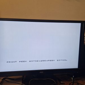
(Ignore the L at the end – that is the cursor but not inverted!)

Ok – press enter and lets see what we get – we should be seeing 65536 (48K)
If it only shows 32782 then this would indicate that it’s either a 16K spectrum, or the upper ram in a 48K is faulty

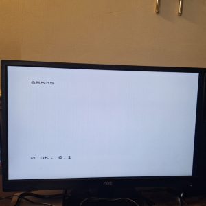
Excellent – we have all the RAM!

We now have a working spectrum!

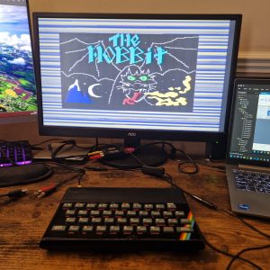
To finish off time to load a game and go back in time to my youth..

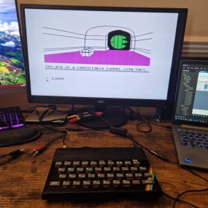
And there we go. For this test, I was using a TZX file, that I converted to a WAV file and then with the EAR socket of the speccy connected to my headphone socket on the PC, I could then use Audacity as a Cassette player and load the game.

And there we go – a fully restored speccy that was built in the early 1980s working again in 2024 – over 40 years later…

Spectrum 48K Repair – Part 2

Welcome to part 2 of this series where I try and repair my first ZX Spectrum.

So far, we’ve installed the Composite Mod and managed to get it boot, but not been able to get much else due to a broken keyboard membrane

Well that finally arrived today – and here it is:

(Excuse the dirty mat underneath – I really should clean that some day)

This came from ZX Renew and is about £8 + P&P so not bad really

Installing is a bit tricky – the first task was to remove the face plate – being careful not to bend it too much

Once done, it was time to clean off all the glue and give the rubber key mat a good wash and a scrub to get rid of the 40+ years worth of grime that had built up – lovely!

And whilst they are drying all that was needed was to slide out the old and knackered membrane and put the new one in its place.

Super easy – so easy in fact I forgot to take pictures – ah well!

Anyway with that in place and the mat dried and put back on it was time to stick the faceplate back on – some double sided tape should do the trick here

And here we go – I powered it on and was able to type out the first line of a program

Lovely, ok lets press enter and get the next line in..

Oh dear.. that isn’t supposed to happen..

This doesn’t look good at all – time for some more trouble shooting.

First up the 7805 voltage regulator – this should read 12V on the left leg, and 5V on the right leg
Results: 10.2V on the left and 5 on the right – that looks good to me – next – the voltage pins on the lower ram modules

The pins we are interested in are the 4 corner pins and should read -5V on the top left, 0V on the Top Right, 5V on the bottom right and 12V on the bottom left

And here we have a couple of problems
I was reading 0V on the -5V pins, and 9.5V on the 12V pins

I reached out on the MFMI Discord server and was told that the chances are that TR4 or TR5 are a goner

So, I’ve ordered one of each and will probably just replace both of them and report back when done
Thanks to Royal Mail – this will take a few days so see you then!

Spectrum 48K Repair – Part 1

So after purchasing a faulty ZX Spectrum 48k, it’s time to start trying to get it up and running.

Task 1 – Composite Mod

From my previous post, we know that it needs at least a composite mod so we’ll do that first. This is actually fairly simple to do and there are a ton of videos on YouTube that walk you through the process 

I would recommend heading over to the likes of More Fun Making It or Happy Little Diodes who both have a great selection of videos on speccy’s and the composite mod. 

All you are really doing is disabling the current RF signal and putting a capacitor in it’s place. It’s well worth doing as most modern tellies don’t usually have the old analogue input anymore. 

Once done it should look something like this

Anyway with the mod in place, it was time to put it all back together and power it up.

And this is what happened: 

Well that was a lot more than I was expecting. 

This is good news, it should mean that the majority of the components are good – specifically, the ULA, the ROM, the Z80 and the lower ram chips.

I won’t know any more until I can replace the keyboard membrane.

My first ZX Spectrum 48K Repair Project

Well, I’ve finally managed to get my hands on a ZX Spectrum 48k with a view to repairing it as it was listed as not outputting any type of display.

It came with the RF lead and the original PSU, as well as a couple of cassettes.

The speccy itself is actually in rather decent condition with only a couple of minor dents on the front of it.
It is dirty, again not unexpected given its age.

Inside, we can see that it is an Issue 3 board and, again, it is in pretty decent condition with no evidence of any prior work being done to it.

Unfortunately, the keyboard membrane didn’t survive me taking it apart so this will need to be replaced in the event we get it up and running.

Now the fun starts as we try and troubleshoot what the issue is. First order of business will be to do a cursory check of all the capacitors and chips to ensure that there is nothing obviously leaking, damaged or missing.

My rough list of objectives will be to:

  1. Test the 7805 to ensure it is supplying the correct voltage, as I understand this is a common issue
  2. Check the ULA – as I don’t have a diagnostic cart, initially this will probably be with a multimeter and oscilloscope
  3. Do a composite mod. That way I don’t need to worry about having a TV that takes the old AV input.